

What is a Boundary Diagram?
One of the first stages of the design process is to define the scope of the project. Life teaches that this stage is not all that simple and obvious. I know of several examples where huge delays in the project were caused precisely by misunderstandings and lack of a clearly defined scope.
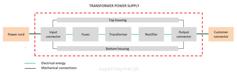
Early in the process of designing a new product, a block diagram should be developed, showing the product concept in a simplified form. The individual "blocks" are subsystems or components of the designed product. The interrelationships between the blocks should also be shown and the interactions "with the outside world" should be included.
Next, we define the boundaries between the blocks that fall within the scope of the design and other external elements. This creates a boundary that defines the scope of the design.
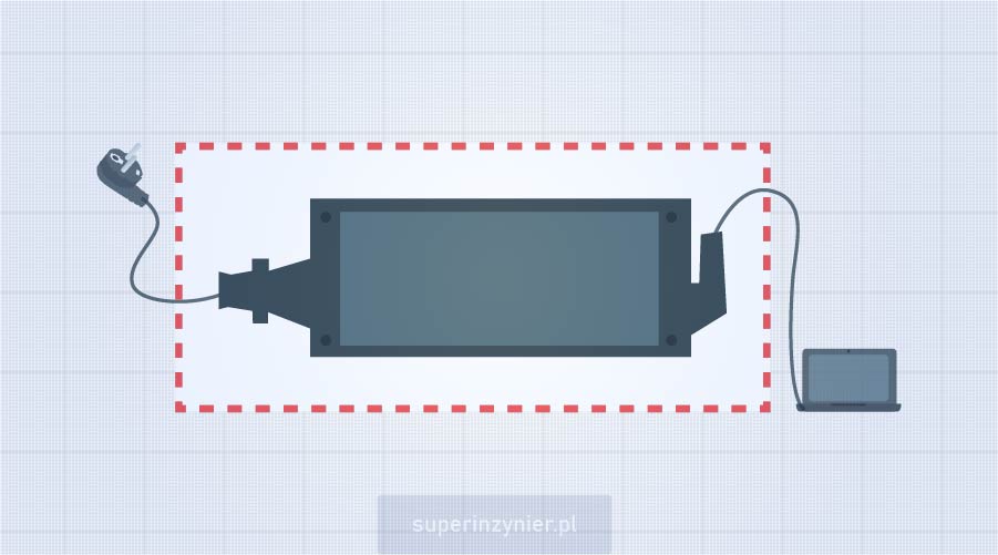
Example Boundary Diagram for a transformer power supply:
Sometimes when creating a diagram, we find that we do not know all the interfaces between the customer's systems and our product. Often, we also don't know what is in the vicinity of our product that can adversely affect its performance. For example: our product will be near a device that emits a strong alternating magnetic field, which may interfere with the operation of our product. We try to obtain such information and place it on the Boundary Diagram accordingly.
Benefits of Boundary Diagram
A correctly prepared Boundary Diagram has a number of advantages:
- We learn the scope of the project, which means we reduce the risk of misunderstandings with other project teams or the customer. This is a very important aspect and very costly if it is not properly worked out at the beginning of the project.
- Boundary Diagram allows you to "divide" a larger system/product into smaller, easier to analyze components.
- Developing a Boudnary diagram helps define the correct nomenclature of the various elements, i.e. organize the terminology in the FMEA team.
- We can more easily identify the main connections (interfaces) between blocks, which is crucial when defining functions and requirements later.
Tools
Boundary Diagram can be easily prepared in a spreadsheet :)
Summary
The boundary diagram should be prepared by the team at the initial stage of the D-FEMA analysis. This is a key document that defines the scope of the analysis, interfaces and subsystem/element breakdown. The boundary diagram is the basis for further activities related to a properly conducted D-FMEA analysis.
