 Polski
 English
Introduction
Electrical connectors play a key role in the operation of electronic systems, enabling the transfer of signals or power between different circuits. The reliable operation of these connectors is closely linked to maintaining sufficiently low contact resistance.
The use of the right type of finish (plating) on the electrical contacts is one of several key aspects of maintaining low contact resistance.
The finish serves as a protective layer on connector surfaces, addressing issues such as contacts corrosion resistance, conductivity and durability. The choice of finish material is a complex decision, depending on the specific application, environmental conditions and the types of metals being used.
This article discusses typical solutions, advantages and disadvantages of different materials and suggests their application.
Structure of an Electrical Connector
An electrical connection made through a connector relies on the electro-mechanical contact between the terminals of the male and female sides. The transfer of electrical energy takes place in the contact zone, where the surfaces of the two terminals of the connector come into contact. The terminals are covered with a suitable protective layer known as plating (or finish).
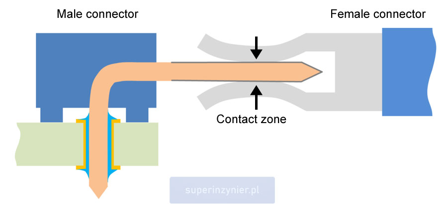
The contact zone is the area where the actual electrical connection occurs. A closer look at this area reveals several layers of different materials. The selection of these materials depends on the purpose of the connector. The primary material of the contact is the so-called base material. In the contact zone, there is a thin layer of finish (final plating). Some connectors also utilize an underplate (intermediate layer), serving an additional protective function.
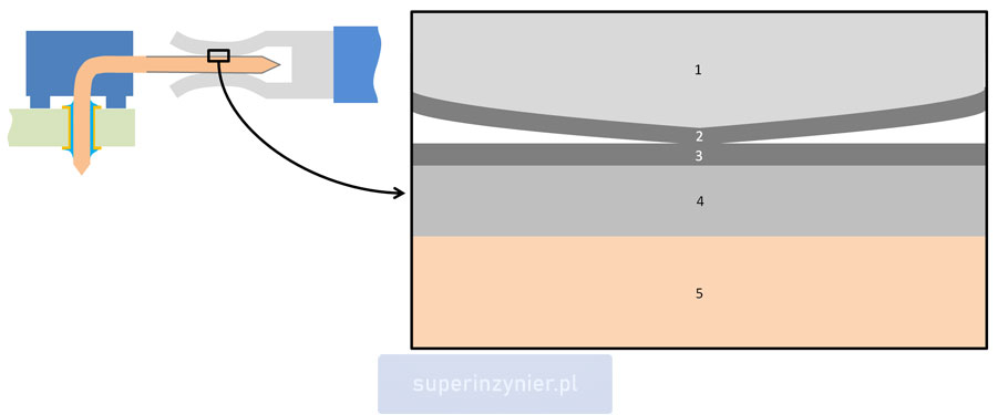
For example, the illustration below depicts the contact zone containing several materials:
- Base material of the female connector
- Finish of the female connector
- Finish of the male connector
- Underplate, used in some solutions
- Base material of the male connector
The SEM microscope image below illustrates the electrical contact zone, in which the individual layers of material are clearly visible:
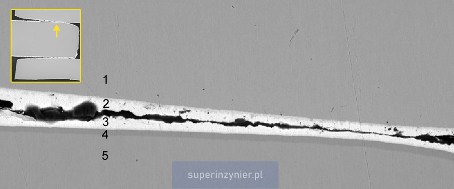
A female connector's base material (1) is copper, followed by a thin layer of tin finish (2) that joins the tin finish of a male connector (3). Underneath there is an underplate of nickel (4) applied to the brass base material of the male connector (5).
Types of finish
The contact finish serves as protection of the base metal against corrosion and reduces the formation of adverse surface films. The protective finish should cover the entire contact area and be corrosion resistant.
Layers of oxides, sulphides or chlorides increase the resistance of the contact, so the reduction of these compounds is crucial to ensure a proper electrical connection. Finish can be done using noble metals such as gold, palladium, silver or non-nouble metals such as tin or nickel.
The most common types of the finish:
Tin
- One of the advantages is the low cost of this element, significantly increasing the popularity of tin.
- Tin finish on leads mounted to PCB facilitates soldering when using standard (low activity) soldering fluxes in electronics.
- The surface oxidation of this metal occurs very rapidly. The tin oxide layer has minimal thickness, as the growth process naturally limits itself at a certain point. Maintaining good electrical contact on the tin layer requires "breaking the oxide layer" through a higher current/voltage or through a sufficiently large mechanical pressure.
- A low contact force in the contact area and the so-called "micro-motion" of contacts can lead to "fretting corrosion" phenomenon.
- Pure tin can be a source of tin whiskers phenomenon, so certain hi-rel related standards prohibit the use of "pure tin" in military and aerospace applications.
Nickel
- Low cost, similar to tin.
- High resistance to wear and corrosion.
- The surface oxidation deteriorates the quality of the connection, so for signals with low amplitude/current this type of plating may pose a challenge.
- Typical (low activity) soldering flux in electronics may struggle with effectively removing nickel oxides during the soldering process. Therefore, soldering nickel-plated leads can be difficult.
Silver
- A noble metal with the highest electrical and thermal conductivity among all metals, a definite advantage of this element.
- Contact with gases containing sulfur causes the formation of silver sulfide (tarnishing), significantly increasing resistance.
- A higher current/voltage causes the "fritting" of the silver sulfide layer, which cannot be achieved by a low-current/voltage electrical signal.
- Suitable for connectors where a higher current or voltage is transmitted, capable of burning off the silver sulfide layer.
- Not recommended for connectors carrying low-current or voltage electrical signals that may not be able to burn off the silver sulfide layer.
Gold
- A noble metal that does not form oxides. Resistant to adverse environmental conditions such as moisture, corrosive gases, etc.
- In its pure form, gold is a soft material, so it wears easily. The addition of nickel (Ni), cobalt (Co), or iron (Fe) increases hardness. A mixture of gold with other elements is referred to as "hard gold".
- The thickness of the gold layer and additives have a crucial impact on the connection's lifespan and the number of mating cycles. Typical gold thickness is 0.4-0.8μm in telecom solutions. Greater thicknesses are used in more demanding applications.
- If the gold layer is very thin (around 0.25μm), this coating is known as "flash gold". Such a layer may sometimes be porous, allowing the material beneath the gold (e.g., nickel) to come into contact with the environment (oxygen and other gases). As a result, metal oxides or other compounds may appear, increasing contact resistance and degrading the quality of the electrical connection.
- The drawback of gold is its high cost.
- An excellent material for the transmission of weak electrical signals.
- The solderability of the gold surface is very good. If the gold layer thickness is significant, in some cases, the soldered connection may become brittle due to an excessive gold concentration. This phenomenon is known as "gold embrittlement."
Gold + Palladium/Nickel
- A coating consisting of two layers. A thin layer of hard gold (e.g., with a cobalt additive) applied on a palladium-nickel (80/20) layer.
- The thin gold layer allows for cost reduction.
- A durable coating, resistant to tarnishing due to the gold layer.
- In applications involving significant wear (e.g., frequent mating/unmating), the gold layer may wear off. Further wear on the exposed palladium layer may lead to the formation of an insulating material known as "brown polymer" if trace amounts of organic compounds are present in the contact environment. The addition of nickel aims to limit this phenomenon. Therefore, a coating with only palladium is sensitive to wear, while a palladium-nickel alloy coating is much more resistant.
- Low resistance of gold-plated contacts and low surface porosity due to the palladium-nickel layer allow the use of this coating in connectors where a low electrical signal is transmitted.
Underplate
Underplate is an intermediate layer between the finish (final plating) and the base material of the connector. This layer is employed in some connector designs.
Typically used materials:
Nickel
- Serves as an excellent diffusion barrier, preventing the base material, such as copper or copper alloys (bronze, brass), from diffusing into the final plating (e.g., gold). It is not a perfect barrier, as nickel intermetallic phases with the final plating may form, but this process is much slower compared to copper.
- Enhances the mechanical strength of the contact in terms of mechanical pressure/deformation.
- Levels the surface of the base material, increasing the wear resistance of the finish.
- Increases corrosion resistance. Nickel is much more corrosion-resistant than the base material, such as copper or its alloys. Therefore, nickel, together with the final plating, provides greater longevity to the contacts.
- The typical thickness of the nickel layer is 1.25-2.5μm. A layer that is too thin may peel, while one that is too thick may crack.
Copper
- Levels the surface of the base material, increasing the wear resistance of the finish.
- Does not provide protection against the diffusion of copper and the finish, making it a much less effective solution than a nickel layer.
Silver
- Currently very rarely used, applied in the past (1960s).
Summary
In the field of electrical connectors, the choice of finish is crucial. This material directly affects the connector's ability to maintain signal integrity, resistance to environmental exposures, and long-term reliability.
It is worth remembering that connectors used in electronics are usually standard catalog parts. Some manufacturers also offer the possibility of creating custom connectors tailored to the needs of a specific application, such as special contact coatings, different pin shapes, sealing, etc. Ensuring quick prototyping and technical support are key aspects in such cases. An example is the offer from the distributor Masters Sp. z o.o., particularly Amtek connectors.
Engineers should carefully consider the application requirements, as an incorrect choice of finish/plating can lead to critical failures in electronic systems. Through a comprehensive understanding of the properties of individual materials and potential types of corrosion, engineers can enhance the connector's resistance to environmental influences. The correct selection of contact finish material has a crucial impact on the reliability of electronic devices.
