
 Polski
 English
Introduction
Tin whiskers are single-crystal tin filaments that grow spontaneously from a tin surface, with a diameter on the order of a fraction of a mil (single micrometers) and a length ranging from a couple of mils (tens of micrometers) up to as much as a tenth of an inch (several millimeters).
Sounds harmless.. until one of these "whiskers" bridges two adjacent leads and knocks an electronic device out of commission. This is a real problem, especially for devices that can't easily be serviced... because, say, they happen to be orbiting the Earth.
The "whisker" phenomenon is nothing new. It was documented back in 1946 (cadmium whiskers in air-variable capacitors) and has been studied since the early 1950s[1,8]. In the 1990s, the U.S. military modified most of its component specifications, banning pure-tin finishes precisely to limit the risk of "whiskers"[2]. The problem came roaring back after the introduction of the RoHS directive (2006) in EU, which forced a large part of the industry away from tin-lead solder (Sn-Pb). Lead, though environmentally harmful, turned out to be an effective inhibitor of tin whisker growth. Eliminating lead meant a return to nearly pure-tin finishes and a surge in tin whisker occurrences.
This is a classic reliability problem, not a manufacturing one. A tin whisker can sprout months or years after assembly, out in the field (in service), when the consequences are far more expensive. That is why high-reliability industries - aerospace, space, defense, medical, and automotive - take the threat very seriously.
To close out the introduction.. let the Galaxy VII (HS-601) satellite failure in 1998 stand as the symbol of this problem, where tin whiskers in a relay led to an electrical short and the loss of the satellite - a loss measured in millions of dollars. That event prompted NASA Goddard Space Flight Center to issue[2] the NA-044 and NA-044A industry advisories.
What Do Tin Whiskers Look Like?
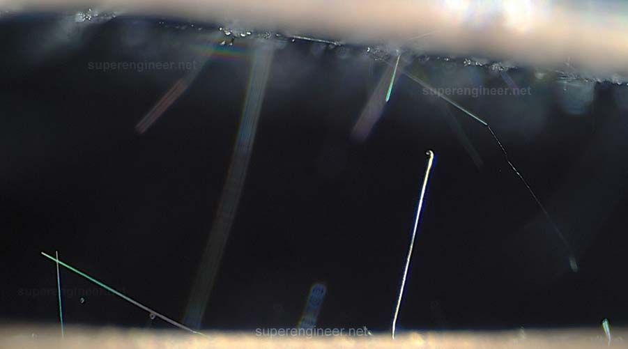
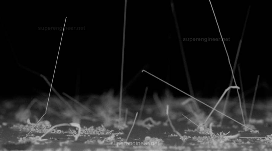
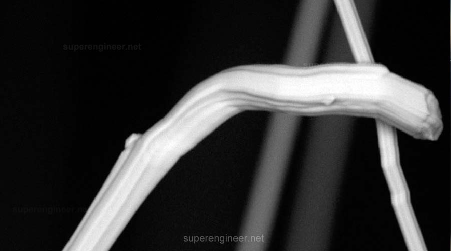
Below are several images I captured using an optical microscope and SEM (Scanning Electron Microscope). Tin whiskers can exhibit remarkably interesting morphologies:
How Do Tin Whiskers Form?
It is worth starting with an honest caveat that every serious publication repeats, including NASA's own materials[2,5] - the complete, universal mechanism for predicting tin whisker growth is not 100% understood.
Most commonly[8], tin whiskers are taken to be the result of compressive stresses in the pure-tin layer, though many other contributing factors are also considered.
Tin under compressive stress tends to release that energy, and one of the relaxation mechanisms is the local diffusion of tin atoms - into grains at higher temperatures and along grain boundaries at lower temperatures. This diffusion "pushes" tin atoms out of the surface, and a whisker forms.[6]
There is also a characteristic temperature window. Growth is intense around 120°F and stops above 300°F.
The key sources of stress that can initiate tin whisker formation are:[2,6,8]
- Residual stress from the plating process. Electroplated (electrolytic) finishes are the most susceptible, owing to the high current densities involved during plating.
- Mechanical stress after plating. Bending of tin-plated leads, pressure in press-fit connections, crimping, tightening screws, and so on.
- Irregular growth of Cu-Sn intermetallic layers. At the tin-copper interface, a Cu-Sn intermetallic compound grows unevenly, generating local compressive stresses. This is one of the dominant mechanisms for tin-plated leads on a copper base.
- Coefficient of thermal expansion (CTE) mismatch. Selecting an unsuitable base material with a CTE significantly different from that of tin. Tin whiskers have also been observed with "rather unusual" base materials such as mica, glass, and paper.
- Scratches in the tin layer. Scratches and defects in the tin layer caused by improper handling.
Whiskers are not limited to tin alone. Analogous structures are observed for zinc, cadmium, and other metals. Tin is very common in electronics, so tin whiskers are most often encountered there.
Tin Whiskers in Electronics
In engineering practice, the risk of tin whiskers concentrates where pure tin is present and the substrate generates stress or additional mechanical strain. Tin whiskers grow spontaneously (no electric field or moisture is required). They can form shortly after manufacturing or only after years of device operation.[2].
Tin whiskers can occur in modern electronics using so-called COTS (Commercial Off-The-Shelf) components. COTS elements are standard electronics available in manufacturers' catalogs for typical applications. COTS are prone to tin whisker formation because their leads are RoHS-compliant and often coated with pure tin.
According to GEIA standards, electronic components and modules can be divided into so-called COTS (Commercial Off-The-Shelf) and ADHP (Aerospace, Defense, High Performance). In ADHP applications, COTS components are also used, despite their intended use in the commercial sector. In such a situation, even when COTS components are soldered with Sn-Pb solder (containing lead, which normally prevents tin whisker formation), there is a risk of tin whisker formation on the portion of the lead where pure tin remains after soldering. Therefore, in ADHP applications, the requirements of GEIA-STD-0005-1, GEIA-STD-0005-2, etc., are applied to reduce the risk of tin whiskers.
Electronic components most susceptible to tin whisker formation include:
- Component leads finished with pure tin. Especially "fine-pitch" designs, where spacings are small and a tin whisker does not have to grow far to bridge adjacent leads. Connector leads may be particularly vulnerable, which is why the selection of appropriate connector contact plating is critical.
- PCBs with an Immersion Tin finish. This type of PCB finish is a thin layer of pure tin (Sn) over a copper pad.
- Electromagnetic relays. Historically the most frequent culprit behind serious failures (whiskers on the contacts) in the space industry.
- Transistors in metal TO packages. Shorts from the collector to the metal case have been documented.[6]
- Cable terminals and terminal blocks, press-fit connectors. Here tin whiskers form because of mechanical stresses that - obviously - arise from the assembly process itself.
The failure mechanisms are twofold. The first is a short (bridging) - transient or permanent, depending on the available energy. The second, far more dangerous, is an electric arc formed from the vaporized metal of a tin whisker. At a sufficiently high voltage and current, the whisker vaporizes first, creating a conductive plasma that then sustains the flow of currents of a far greater magnitude.
Mitigation - What to Do..
The industry consensus is clear: there is no single, simple way to guarantee that tin whiskers will not grow. Therefore, a "defense-in-depth" strategy is used, comprised of three pillars: good material practices, process control, and verification testing. In critical applications (ADHP), it is usually required to employ at least two independent mitigation techniques (e.g., proper material selection + conformal coating).
The most important techniques:
- Tin-Lead finish. In industries covered by RoHS exemptions (aerospace, defense, space, some medical applications), tin-lead solder remains the most effective and simplest barrier. Lead at a level of >3% practically blocks the occurrence of tin whiskers. PCBs can be ordered with an Sn-Pb finish, and Sn-finished components can be put through a "Hot Solder Dip" procedure, that is, dipping the leads in molten Sn-Pb[2].
- Matte tin instead of bright tin. According to industry reports, a matte tin finish has a larger grain size and, therefore, lower internal compressive stresses than a glossy tin finish. Mate finish may reduce tin whisker formation by more than a factor of ten.[7]
- Alloying additives in tin. Tin finishes with additives such as bismuth reduce the risk relative to pure tin.[7]
- Nickel barrier. Matte or reflowed tin over a nickel underlayer reduces copper diffusion and lowers the risk of whiskers.[7]
- Post-plating bake (annealing). An additional heat treatment for tin over copper reduces residual stresses.
- Noble-metal finishes. Au over Pd/Ni or Au over Ni eliminate tin whiskers.
- Conformal coating. A protective coating slows tin whisker growth and limits the risk of a short (bridging) to adjacent leads. Conformal coating is a stopgap, not a solution. Tin whiskers can pierce very thin or unevenly applied coatings. NASA explicitly warns that for long-duration missions, conformal coating as the sole mitigation measure may be insufficient. Coating is one of the two "layers of defense" against this phenomenon.
- Extended design margin. Increasing conductor spacing where the design allows reduces the risk of a failure even if tin whiskers do appear.
A side note: NASA has reported[6] that adding lead to tin significantly reduces the tin whisker phenomenon but does not eliminate it entirely.
Standards
The more important documents that address tin whiskers:
- IPC/JEDEC JP002 Current Tin Whiskers Theory and Mitigation Practices Guideline.
- JEDEC JESD22-A121 Measuring Whisker Growth on Tin and Tin Alloy Surface Finishes.
- JEDEC JESD201 Environmental Acceptance Requirements for Tin Whisker Susceptibility of Tin and Tin Alloy Surface Finished.
- GEIA-STD-0005-1 Standard for Developing a Lead-Free Control Plan to Manage the Risks of Lead-Free Solders and Finishes in Aerospace, Defense, and High-Performance Soldered Electronic Products.
- GEIA-STD-0005-2 Standard for Mitigating the Effects of Tin Whiskers in Aerospace and High Performance Electronic Systems.
- NASA Advisory NA-044 / NA-044A NASA PARTS ADVISORY - Tin Whiskers
Summary
Tin whiskers are a classic example of a problem that is easy to dismiss at the design and production stage, because it does not show up on the assembly line or in final testing. It shows up later.. sometimes after many years, out in the field (in service), where the cost of failure is very high, and in extreme cases it can be catastrophic.
From an engineering standpoint, it is worth remembering that the formation mechanism of tin whiskers is not fully understood, growth can be unpredictable, and no single measure (conformal coating included) offers a 100% guarantee. That is why the industry standards (JEDEC, IPC, SAE/GEIA, NASA guidelines) consistently promote a multilayered approach: selecting low-risk materials, controlling the process, deliberately avoiding pure tin in critical applications, and testing.
For the quality and product engineer, the practical takeaway is simple: the risk of tin whiskers should be addressed as early as possible, during the component selection and process definition stage. Favor no-tin materials, nickel barriers, alloying additives, and - where it is permitted - the use of Sn-Pb.
High-reliability industries (ADHP) have shown that the problem can be managed - not by hoping that "it won't happen to us," but through discipline in design, materials selection and process control. The physics of whiskers can't be "switched off by an EU directive ;-)"; instead, the risk has to be brought down to an acceptable level - provided it is taken seriously early enough.
Footnotes
- K. G. Compton, A. Mendizza, S. M. Arnold — "Filamentary Growths on Metal Surfaces - Whiskers", Corrosion, Vol. 7, No. 10, 1951.
- NASA Goddard Space Flight Center, NASA Advisory NA-044. https://nepp.nasa.gov/whisker/reference/tech_papers/na-044.pdf
- https://www.flightglobal.com/airframers/2000/12/control-fault-knocks-out-galaxy/
- https://nepp.nasa.gov/whisker/reference/reference.html
- https://nepp.nasa.gov/whisker/
- https://nepp.nasa.gov/whisker/reference/tech_papers/2012-Panashchenko-IPC-Art-of-Metal-Whisker-Appreciation.pdf
- https://www.indium.com/blog/tin-whiskers-iv-mitigation-2/
- JEDEC/IPC JP002. JEDEC Solid State Technology Association, Arlington, Virginia, and IPC, Bannockburn, Illinois. USA. 2006.
