

Introduction
Lead soldering was a common practice in the electronics industry for years, providing reliable solder joints in various devices. However, over time, concerns have been raised about the impact of this type of soldering on human health and the environment, leading to restrictions on its use. Lead free alloys were introduced. This article aims to discuss lead based soldering, which, although now subject to restrictions, is still used in some cases.
Types of lead alloys
Lead alloys in the electronics industry are listed in standard J-STD-006. Depending on the lead/tin ratio and the addition of other elements, solder with different melting points and mechanical strength can be obtained. The most common additions of other elements are silver (Ag) or bismuth (Bi). Less commonly, antimony (Sb) or indium (In) were used.
Materials are typically available in the form of wires, flat bars, and solder pastes for SMT soldering.
The most common types of lead alloys used in the electronics industry:
Tin / lead
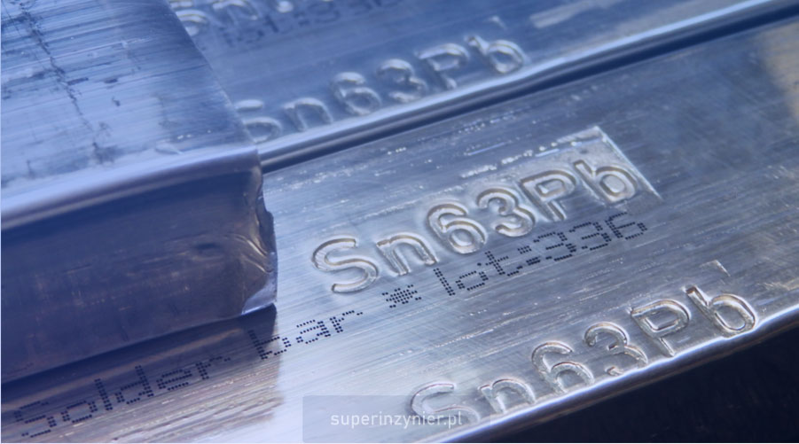
The most commonly used lead-based soldering material in electronics. A popular eutectic alloy is Sn63Pb37 (63% tin, 37% lead), which has a melting point of 183C. Sn60Pb40 alloy is also used, but it is not eutectic and has a melting temperature between 183-191C.[1]
Tin / lead / silver
The addition of silver increases mechanical strength and slightly lowers the melting point. For example, Sn62Pb36Ag2 alloy is a eutectic solder with a melting point of 179C. It is most often found in the form of SMT solder paste.
Tin / lead / bismuth
Bismuth in tin-lead alloy results in a lower melting point, which is clearly an advantage because it reduces thermal stress on components. On the other hand, a disadvantage compared to tin-lead alloys is lower resistance to thermal stress, so it is not recommended for applications with higher operating temperatures.
For example, Sn34Pb20Bi46 alloy (46% bismuth) is eutectic, and its melting point is 100C. In contrast, the Sn43Pb43Bi14 alloy (14% bismuth) is not eutectic, its melting temperature in range of 144-163C.[1]
Interestingly, bismuth in small amounts added to tin-lead solder improves the mechanical properties of the solder without significantly lowering the soldering temperature.[1]
Eutectic alloy
The name "eutectic" comes from the Greek word "eutectos", which means "easily fusible".
A eutectic alloy is a solder alloy that has the same melting and solidification temperature and, of course, at the lowest melting point. A good example is Sn63Pb37, which melts and solidifies at 183C. This melting point is much lower than the melting temperature of the pure metal, which is 232C for tin and 327C for lead, respectively.
The phase diagram of tin and lead below shows the relationship between the two elements and the states of matter. The point marked 183C is exactly the lowest temperature at which the liquid phase and the solid phase meet simultaneously; there is no transition phase.
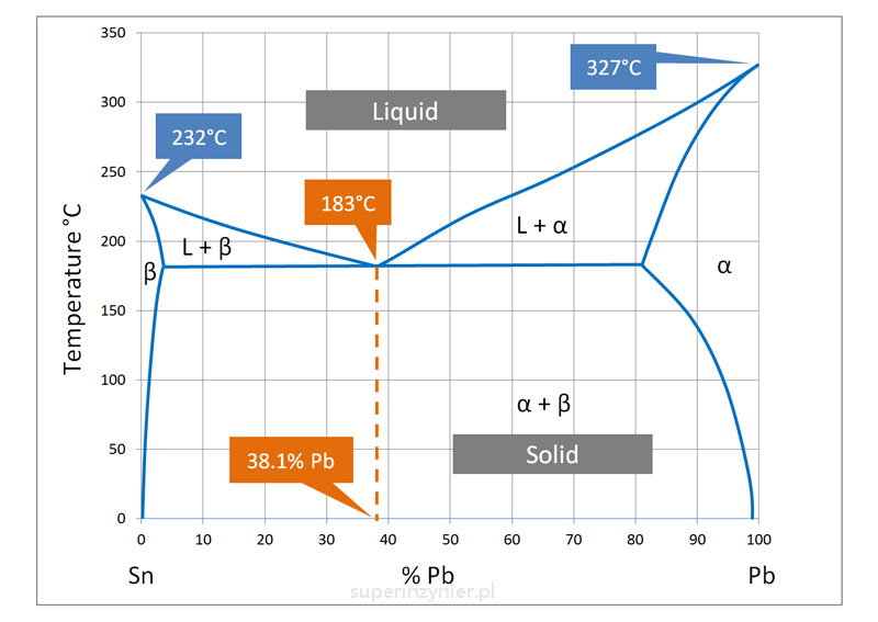
Interestingly, the ratio of tin to lead at this point is exactly 61.9/38.1, not 63/37. In that case, why is the Sn63Pb37 alloy referred to as eutectic? It turns out that tin oxidizes slightly faster than lead and binds slightly faster to the base material of the surface to be soldered, so a small excess of tin is helpful in practical achieving the lowest melting point.[2]
Eutectic alloys allow a faster soldering process because the change in state of matter is very rapid, and the alloy in its completely liquid form more easily wets the surfaces to be soldered and solidifies uniformly. The eutecticity of the alloy results in locally uniform solidification of the solder, creating a smooth solder surface. Therefore, eutectic alloy tends to create smooth, shiny solder joints.
Appearance
Lead solder, compared to most lead-free alloys, has a shinier and smoother surface and a lower wetting angle. Such features facilitate visual inspection of solder joints in the electronics industry.
You can read more about the wetting angle in the article about Soldering: Introduction and in the article about nonwetting effect.
Alloy impurities
If the solder alloy is in a pot or soldering bath, it is worth remembering that it may be contaminated with other elements. This can change the mechanical properties of the alloy and its melting and solidification temperatures.
These elements can come from the walls of the pot, the solder bath or simply from the surface of the materials being soldered. For example, the contact of liquid solder with the copper pads of a PCB during wave soldering causes copper to dissolve and diffuse into the alloy in the bath. It is the copper dissolution effect. It increases the percentage of copper in the solder alloy and changes the solder parameters.
Industry standards specify the maximum level of impurities that can be present in a given type of solder alloy. When using a solder pot or wave solder bath, the level of impurities in the solder alloy should be tested periodically.
Standardy przemysłowe określają maksymalny poziom zanieczyszczeń, jaki może wystąpić w danym rodzaju stopu lutowniczego. Stosując procesy lutowania oparte o tygiel lub wannę, należy okresowo badać poziom zanieczyszczeń w stopie lutowniczym.
Legal constraints
Lead-containing alloy has a negative impact on the health of those who come into contact with it in the manufacturing process. In addition, electronic scrap containing lead alloy is one of the causes of heavy metal contamination of water. These hazards have led to changes in regulations in many countries. The following are the main regulations:
RoHS in the European Union
The RoHS Directive[3] was adopted by the European Union and came into force on July 1, 2006 as Directive 2002/95/EC. Its scope covers a wide range of electronic products, including household appliances, computer equipment, cell phones, telecommunications equipment, industrial electronics, electronic toys and many others.
The main substances banned under RoHS are lead, mercury, cadmium, hexavalent chromium, bromine in the form of organic compounds and some phthalates. Lead is one of the most harmful elements and has been widely used in the electronics industry as a component of solder.
On July 21, 2011, Directive 2011/65/EU, known as RoHS 2, came into force. Compared to its predecessor, RoHS 2 not only expanded the scope of products covered, but also imposed new obligations on manufacturers, such as preparing EU declarations of conformity and affixing CE marks to finished products. The directive also includes annexes detailing product groups covered by exceptions.
RoHS in China
China has a regulation known as China RoHS [4], which aims to control the use of hazardous substances in electrical and electronic products. China RoHS I was introduced in 2006, and its updated version, China RoHS II, has been in effect since July 1, 2016.
China's RoHS II directive covers electrical and electronic products (EEPs), which must meet limits for hazardous substances such as lead, mercury, cadmium, hexavalent chromium, polybrominated biphenyls (PBBs) and polybrominated diphenyl ethers (PBDEs), unless they are on an exception list. All products imported into China must be labeled to indicate whether they meet the requirements for hazardous substances.
USA
In the United States, there are no regulations restricting the use of lead at the federal regulatory level (in 2023). However, there are regulations at the state level, such as in California. As a result, electronics manufactured for the U.S. market may still (but not necessarily) rely on lead solder.
Advantages of lead soldering
- The low melting point (about 183C) allows soldering at lower temperatures than with the common lead-free alloys. This significantly reduces thermal stresses on components.
- The alloy's lower melting point makes it easier to use, especially for hand soldering and soldering components with high thermal mass that are difficult to heat.
- Lower cost of electricity needed to melt the alloy
- The surface of the soldered joint is shiny and easy to evaluate during quality control.
- Lead solder has been used from the very beginning of the electronics soldering process, allowing for the preservation of a known level of reliability. This is crucial in some critical applications.
- There is no phenomenon of tin whiskers, which can occur in lead-free alloys.
- It is cheaper than popular lead-free alloys and does not require the addition of silver.
Disadvantages of Lead Soldering
- Toxicity: It contains lead, which is harmful to solderers. Inhaling lead solder fumes or exposure to solder dust can lead to serious health issues. Lead can accumulate in the human body over the years.
- Negative Environmental Impact: Electronics subject to recycling can release lead into the water, posing a threat to human health and the entire ecosystem.
Summary
Lead solders have been used in soldering since the early days of electronics production and offer several technological and reliability advantages. Unfortunately, they have a significant drawback related to their negative impact on health and the environment. The use of lead solder is gradually being phased out. In facilities where both lead and lead-free soldering are used, care should be taken not to mix materials and not to use the same tools (e.g., soldering tips) for both types of alloys.
The use of lead solders is slowly becoming obsolete, but a basic understanding of the topics discussed in this article will be useful regardless of the soldering material used.
Additionally, it is important to select the correct soldering flux. For reflow soldering, it's important to use the best SMT soldering profile. For wave soldering, it's important to use the right THT soldering profile.
References
- IPC J-STD-006
- K. Sweatman. Fact and fiction in lead-free soldering. Global SMT & Packaging. April 2006
- https://environment.ec.europa.eu/topics/waste-and-recycling/rohs-directive_en
- http://www.cesi.cn/rohs/page/index.html
