 Polski
 English
Introduction
Fault Tree Analysis (FTA) is a method used to identify and evaluate cause-and-effect relationships that lead to a specific fault. FTA helps determine which causes should be addressed first—reduced or eliminated—to improve system reliability.
FTA uses a special type of logic diagram that accurately reflects causal relationships and the logical connections between them. This method also enables estimation of the probability of the analyzed fault occurring (so-called quantitative analysis).
FTA is widely used in safety and reliability analysis, especially in the military, nuclear, aerospace, and space industries. It can also be effectively applied when solving technically complex problems within the framework of the 8D Method or its variant Global 8D (G8D). Naturally, FTA is also highly valuable in Design for Reliability (DfR) practices.
This article serves as an introduction to the FTA method. You will learn the basic principles of constructing fault trees, along with a few guidelines and recommended standards.
Enjoy the read :)
History of FTA
- 1962. Between 1961 and 1962, the FTA method was developed by H.A. Watson at Bell Laboratories, commissioned by the United States Air Force (USAF), as part of an analysis of the Minuteman I missile launch control system.[1]
- 1963. FTA was applied by Boeing throughout the Minuteman II program and later used in the design of the company’s commercial aircraft.[1]
- 1965. Boeing, in collaboration with the University of Washington, presented the FTA method at the System Safety Conference in Seattle.[1]
- 1967. After the Apollo 1 mission disaster, Boeing used FTA to improve safety systems within the Apollo program in cooperation with NASA.[1]
- 1970+. The nuclear industry adopted and further developed the FTA methodology, popularizing its use in nuclear power plants.
- 1980+. FTA began to be used in additional industrial sectors, such as the chemical and automotive industries, supporting risk assessment and the enhancement of system reliability.
What is FTA?
FTA is a deductive method, meaning it proceeds from top to bottom—in other words, from a top event (such as a final effect or problem) down to its possible causes.
The FTA method is based on a special type of logic diagram used to construct and analyze what is called a fault tree. Hence the name FTA - Fault Tree Analysis.
In FTA terminology the analysed problem is known as Top Event. It is a result of the all combinations of multiple input events.[2]
Certain events may be classified as outcomes, meaning they are the result of other events occurring. These events may occur in two ways:
- Independently of one another. A single cause is sufficient to trigger the outcome (effect).
- In combination with other events. Multiple input events must occur simultaneously for the outcome to happen. For example, a fire (outcome event) can only occur if fuel, oxygen, and an ignition source (e.g., a flame) are all present at the same time and place. The absence of any of these input events will prevent the fire from occurring.
FTA uses logic symbols based on Boolean logic to accurately model the relationships between events. Many of these symbols resemble the logic gates used in digital electronics, such as AND, OR, and NOT.
FTA Types
FTA analysis can be performed using either a qualitative or a quantitative approach, depending on the required scope of the analysis.[2]
- Qualitative approach involves developing the fault tree structure to understand the cause-and-effect relationships that lead to the top event.
- Quantitative approach builds on the qualitative analysis by estimating the probability of the fault occurring, using available statistical data (e.g., reliability data for components or systems).
FTA Symbols
IEC-61025 allows for different symbols for logic gates and various layouts of the fault tree structure.[2] Therefore, the specific choice of symbols depends on the standards and requirements adopted by the given organization.
Example (selected) event symbols:


Example (selected) logic gates:


FTA analysis may utilize many additional logic gates and symbols, such as: NOT, NAND, NOR, INHIBIT, Priority AND, SEQ, SPARE, TRANSFER, etc. Therefore, it is always important to ensure the correct interpretation of each logic symbol used.
FTA Example
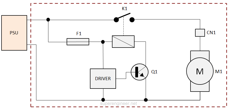
For the purposes of this article, the diagram below presents an electrical circuit in which the electric motor M1 is switched on via relay K1, which is connected to a PSU (power supply unit). Motor M1 is connected to relay K1 through connector CN1. Relay K1 itself is controlled by transistor Q1. The control and power supply to the K1 coil are protected by fuse F1. The analysis boundary is marked with a dashed red line.
The following diagram shows part of an FTA analysis corresponding to the above electrical schematic:

- The Top Event is the loss of power to motor M1 and is marked as event [G1].
- This event may be caused by a power loss from the PSU [H1], or deactivation of relay K1 [G2], or disconnection at connector CN1 due to a loose screw [G3].
- Power loss from the PSU [H1] is classified as an External Event, as it lies outside the scope and control of the analyzed system. Some practitioners may omit it or represent it as a Basic Event, depending on the chosen approach and definitions.
- Deactivation of relay K1 [G2] may result from the shutdown of transistor Q1 [U1] or the blowing of fuse F1 [B1].
- Shutdown of transistor Q1 [U1] is classified as an Undeveloped Event, which may be analyzed in more detail at a later stage. Q1 and its driver have not yet been fully analyzed.
- Blowing of fuse F1 [B1] is a Basic Event, representing the lowest level of analysis in this branch of the fault tree.
- Disconnection at connector CN1 [G3] is caused by insufficient screw torque [B2] and environmental vibration [H2].
- The vibration event [H2] is classified as an External Event (House Event), as it defines an operating condition of the system. The insufficient screw torque [B2] is classified as a Basic Event.
This example is illustrative and serves to demonstrate the FTA method— in practice, fault tree analyses are typically much more detailed and extensive.
Minimal Cut Set (MCS)
MCS (Minimal Cut Set) can be understood as a minimal set of basic events that is sufficient to cause the occurrence of the Top Event.[3]
The main objective of MCS analysis is to identify critical combinations of events that should be eliminated, reduced, or at least monitored. In other words, MCS highlights weak points in the system’s design.
Based on the identified minimal cut sets, it is also possible to perform a quantitative risk analysis (i.e., calculate the probability of the Top Event occurring).
Advantages of FTA
- Clear visualization. A well-developed fault tree can clearly represent complex cause-and-effect relationships that are otherwise difficult to understand.
- Identification of critical items. FTA enables the identification of causes that may be critical to the system’s reliability and safety — as determined through Minimal Cut Sets (MCS).
- Knowledge consolidation. A good FTA diagram serves as a valuable knowledge base for understanding potential failure causes in complex systems.
- Support for both qualitative and quantitative analysis. The method allows not only for understanding causal structures but also for estimating the probability of occurrence.
- Integration with other methods. FTA can be effectively combined with 8D, G8D, and DFR, and can complement data used in D-FMEA.
Disadvantages of FTA
- Time-consuming. Building a detailed fault tree requires a significant amount of time. But to be fair, that’s the case with any solid analysis—so this could be seen as a “standard drawback.” :)
- Challenging for dynamic systems. Analyzing events that depend on timing or sequences is more difficult, although it is possible using special gates such as SEQ, SPARE, or Priority AND.
- More difficult without dedicated software. Creating diagrams strictly in line with the FTA methodology is much easier with specialized tools.
Standards
- IEC 61025 Fault Tree Analysis (FTA). The primary international standard dedicated entirely to FTA.
- NUREG-0492 Fault Tree Handbook. FTA analysis applied to the nuclear energy sector.
- Fault Tree Handbook with Aerospace Applications. A handbook developed by NASA for aerospace use.
It is worth noting that many industry and sector-specific standards reference FTA as a supporting method for safety or reliability analysis, such as: ISO 26262, IEC 61508, MIL-STD-882, and ARP4761.
Summary
FTA is an effective and practical solution, particularly useful in the design of reliable devices. Its history and the industries that rely on it clearly show that FTA is truly an excellent method.
In practice, I occasionally use FTA to analyze complex cases of electronic failures and have found that it complements RCA (Root Cause Analysis), 8D, Global 8D, DFR (Design for Reliability), and D-FMEA extremely well.
In conclusion, FTA is a powerful tool for analyzing and improving product design.
References
- C. A. Ericson II, "Fault Tree Analysis - A History," in Proc. 17th Int. System Safety Conf., 1999.
- International Electrotechnical Commission, IEC 61025: Fault Tree Analysis (FTA), 1st ed., Geneva, Switzerland: IEC, 2006.
- NASA Office of Safety and Mission Assurance, Fault Tree Handbook with Aerospace Applications. Washington, DC: NASA Headquarters, 2002.
