
 Polski
 English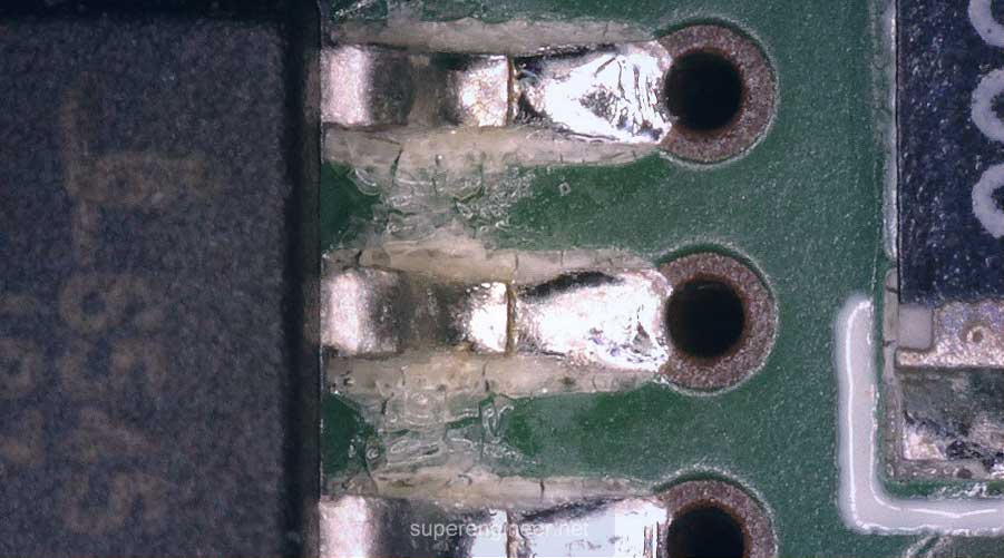
Introduction
Customer: "Boards should be clean after the assembly process." Hmm... sometimes that is exactly the kind of "requirements definition" we get :)
In reality, the cleanliness of assembled boards (PCBA) is a very broad and complex topic. By "PCBA cleanliness," customers may mean ionic cleanliness, non-ionic cleanliness, and sometimes also so-called technical cleanliness. On top of that, for many years ionic cleanliness requirements were based on a limit from the 1970s, which is inadequate for modern electronics.
In this article, I present the main aspects of "assembled board cleanliness," the key industry standards, and a few practical recommendations at the end.
Enjoy the read :)
A bit of history
In the 1970s and 1980s, boards in high-volume production were typically wave soldered with RMA flux and then cleaned with chlorofluorocarbon (CFC) solvents[1]. The most popular cleaning agent was CFC-113 (1,1,2-trichloro-1,2,2-trifluoroethane), sometimes used as a blend with methanol. Less commonly used was methyl chloroform, MCF (1,1,1-trichloroethane).
The same period also saw the development of a method for measuring ionic contamination, with a limit for cleaned boards of 1.56 µg/cm2 [10 µg/in2] NaCl equivalent. The method was developed in the early 1970s by Hobson and DeNoon at the US Naval Avionics Center[1][2]. The limit made its way into MIL-P-28809, then into MIL-STD-2000A and J-STD-001[1]. It is worth remembering that this limit was established for a process using RMA flux and CFC cleaning.
In 1974, Nature published a paper on the threat that CFCs, among other substances, pose to the ozone layer. It showed that chemically inert CFCs reach the stratosphere, where UV radiation breaks them down, releasing chlorine, which then destroys ozone[3]. In 1985, it was confirmed that ozone levels over Antarctica had dropped by about 40% between 1975 and 1984[4]. As a result, the UN took up the issue. The 1985 Vienna Convention and the 1987 Montreal Protocol on Substances that Deplete the Ozone Layer launched a global process of reducing the use of ozone-depleting substances. Over the following years, this led to the phase-out of, among others, CFCs and MCF[5][6]. In the US, production and import of CFCs and methyl chloroform ended on January 1, 1996, under the Clean Air Act. In 2009, the Montreal Protocol became the first treaty in UN history to be ratified by every country in the world[7]. Wow! For once in this planet's history, everyone actually agreed.
Clean and no-clean
The electronics industry had to abandon CFCs. That meant changing fluxes, cleaning agents, and the soldering and cleaning processes themselves. As an interim measure, solvents known as HCFCs were used for cleaning, but these were also phased out[8][9].
Ultimately, two types of processes emerged:
- Clean (board cleaning). Flux residues are removed after soldering using aqueous, semi-aqueous, or solvent-based cleaning. Generally, cleaning is applied to boards soldered with high- and medium-activity organic fluxes (ORHx / ORMx per J-STD-004). Sometimes less active rosin fluxes (type RO per J-STD-004) are cleaned as well. In a "clean" process, the flux is active enough that any residues left after cleaning are considered corrosive, so the board shall be "visually" completely clean and, of course, also have a low level of ionic contamination.
- No-clean (no board cleaning). In this approach, flux residues should be minimal and benign enough to be left on the board surface without cleaning. However, this technology has a "gray zone": for some applications, "no-clean" flux residues may still be active enough to affect product reliability. So "no-clean" residues are sometimes cleaned anyway. In short, the "no-clean" process is popular, but it is not a perfect solution.
Ionic cleanliness
Contamination on an assembled electronic board may contain ions (molecules/atoms carrying an electric charge), which can lead to electrochemical migration (ECM), commonly referred to as "corrosion" or "dendrites." This is the phenomenon that the term "ionic cleanliness" relates to.
Several different methods are used to evaluate ionic contamination:
- ROSE. Resistivity of Solvent Extract. The method is described in IPC-TM-650 2.3.25. Contaminants are extracted with a mixture of isopropanol and deionized water, and the measured resistivity of the extract is converted to a sodium chloride (NaCl) equivalent per unit area. This is the method behind the "famous" 1.56 µg/cm2 [10 µg/in2] NaCl equivalent limit.
- Ion chromatography. The method is described in IPC-TM-650 2.3.28. It identifies individual ions (e.g., chlorides, bromides, weak organic acids) and quantifies them.
- SIR. Surface Insulation Resistance, described in IPC-TM-650 2.6.3.7. This method does not measure the amount of ions; instead, it directly measures their effect, i.e., surface insulation resistance under bias at elevated temperature and humidity.
Ongoing miniaturization of electronics, ever-smaller spacing between leads, the use of low-standoff packages (BGA, µBGA, QFN, LGA), and applications operating in harsh environments have made the 1.56 µg/cm2 NaCl equivalent limit inadequate in many cases.
No-clean fluxes contain weak organic acids (WOAs), which can inflate ROSE results, while at the same time these residues may be acceptable for many applications. In such cases, the 1.56 µg/cm2 NaCl equivalent limit was "too low," i.e., not aligned with reality.
The ROSE method also gives a value averaged over the entire board surface, and may poorly extract contaminants from under low-standoff components, and does not distinguish between ion types (it is not a chromatograph). Studies have also shown that ROSE results do not predict reliability: samples with a ROSE result three times higher showed SIR values that were higher not by a factor of three, but by several orders of magnitude[1].
Due to above reasons, the Global Electronics Association (IPC) changed its approach to ionic cleanliness. First, in 2018, Amendment 1 to J-STD-001G was released. Then, in Revision H (2020), the entire Section 8 was revised[10]. The hard limit from the 1970s was dropped. Now, unless the User (customer) specifies a limit, one must be established based on objective evidence. A ROSE result below 1.56 µg/cm2 alone no longer automatically means the process is acceptable.
The ROSE test is now used for process monitoring, with control limits established during qualification. The detailed rules are given in J-STD-001 Section 8[11].
Non-ionic cleanliness
Contamination on a PCBA is not limited to substances that cause electrochemical migration; it also includes non-ionic compounds: rosin and resin residues from flux, oils from hand creams, silicones, masking material residues, etc. They do not dissociate into ions, so the ROSE method does not detect them, even if they dissolve in the IPA/water mixture.
These residues can, however, degrade the adhesion of conformal coatings, adhesives, and potting compounds to the PCB surface. As a result, moisture and contaminants from the environment can penetrate under a poorly adhering coating and lead to electrochemical migration, shortening the product's service life.
In some cases, unexpected interactions can also occur between flux residues and the coating or potting material, affecting cross-linking (curing).
J-STD-001J, clause 8.6, specifies acceptance criteria for non-ionic contamination.
Technical cleanliness
In industry, especially in automotive, the term "cleanliness" may also refer to so-called technical cleanliness, i.e., the level of particulate contamination (dust, metal chips, fibers, etc.) that can lead to failures such as short circuits.
In automotive, technical cleanliness is based on the VDA 19.1 and ISO 16232 standards (inspection and evaluation of contamination) and VDA 19.2 (cleanliness management in the assembly process).
The test involves extracting (rinsing) the product, filtering the particles onto a membrane, and analyzing them in the lab: microscopic evaluation (particle count and size) and, if needed, SEM-EDS analysis (composition).
Interestingly, in IPC terminology such contamination is referred to as FOD (Foreign Object Debris). According to IPC-A-610, loose particles that may violate minimum electrical clearance are a defect regardless of IPC class.
Standards
- IPC J-STD-001. Requirements for Soldered Electrical and Electronic Assemblies
- IPC-HDBK-001. Handbook and Guide to Supplement J-STD-001
- IPC-A-610. Acceptability of Electronic Assemblies
- IPC-TM-650 2.3.25. Detection and Measurement of Ionizable Surface Contaminants by Resistivity of Solvent Extract (ROSE)
- IPC-TM-650 2.3.28. Ionic Analysis of Circuit Boards, Ion Chromatography Method (IC)
- IPC-TM-650 2.6.3.7. Surface Insulation Resistance (SIR)
- IPC-9202A. Material and Process Characterization/Qualification Test Protocol for Assessing Electrochemical Performance Using the IPC-B-52 Test Assembly
- IPC-WP-019B. An Overview on Global Change in Ionic Cleanliness Requirements
- IPC-CH-65B. Guidelines for Cleaning of Printed Boards and Assemblies
- IPC-5704. Cleanliness Requirements for Unpopulated Printed Boards (bare boards only)
- VDA 19.1. Inspection of Technical Cleanliness - Particulate Contamination of Functionally Relevant Automotive Components
- VDA 19.2. Technical Cleanliness in Assembly - Environment, Logistics, Personnel and Assembly Equipment
- ISO 16232. Road Vehicles - Cleanliness of Components and Systems
Summary
Cleanliness in electronics is a broad term that can be interpreted in different ways.
A board can be visually clean and still carry a high level of ionic contamination, either transparent or hidden in places you can't see (e.g., under an IC package). That's why cleanliness requirements need to be clearly defined: what kind of cleanliness we're talking about (ionic, non-ionic, technical), which criteria apply, which standards, and which measurement methods.
When it comes to ionic cleanliness, keep in mind the changes made to J-STD-001 a few years ago, i.e., dropping the single 1.56 µg/cm2 [10 µg/in2] limit in favor of establishing an ionic contamination limit appropriate for the given application, backed by objective evidence.
One last point: PCBA cleanliness is not just about flux selection and the cleaning process, but also about how boards are handled and stored afterward, all the way up to packaging. Avoid touching PCBAs with bare hands (sweat contains, among other things, sodium chloride) or with dirty gloves. Keep in mind that dirty gloves in particular can give a "false sense of cleanliness." Flux residues are often transparent or white, so they don't show up on white gloves. It may turn out that washing your hands frequently and not using any unapproved hand creams is better than trusting gloves to provide 100% protection, especially when they are rarely changed. Worth remembering..
References
- K. Tellefsen et al., Divergence in Test Results Using IPC Standard SIR and Ionic Contamination Measurements, I-Connect007, 2016: https://iconnect007.com/article/99083/divergence-in-test-results-using-ipc-standard-sir-and-ionic-contamination-measurements/99086/smt?page=1
- ESA STM-275, Evaluation of Cleanliness Test Methods for Spacecraft PCB Assemblies, 2006: http://esmat.esa.int/publications/published_papers/esa_stm-275.pdf
- M. J. Molina, F. S. Rowland, Stratospheric sink for chlorofluoromethanes: chlorine atom-catalysed destruction of ozone, Nature 249, 810–812 (1974): https://doi.org/10.1038/249810a0
- J. C. Farman, B. G. Gardiner, J. D. Shanklin, Large losses of total ozone in Antarctica reveal seasonal ClOx/NOx interaction, Nature 315, 207–210 (1985): https://doi.org/10.1038/315207a0
- IEA, Montreal Protocol – Copenhagen Amendment: https://www.iea.org/policies/20364-montreal-protocol-copenhagen-amendment
- US EPA, Phaseout of Class I Ozone-Depleting Substances: https://epa.gov/ods-phaseout/phaseout-class-i-ozone-depleting-substances
- UN (HLPF), Montreal Protocol – universal ratification: https://hlpf.un.org/inputs/montreal-protocol
- IPCC / GRID-Arendal, Methodological and Technological Issues in Technology Transfer. https://www.grida.no/climate/ipcc/tectran/115.htm
- US EPA, Vendor list: alternatives for CFC-113 and methyl chloroform in electronics cleaning: https://www.epa.gov/sites/default/files/2014-11/documents/sol_elec.pdf
- IPC, IPC Releases New “H” Revision to IPC J-STD-001 and IPC-A-610: https://www.electronics.org/news-release/ipc-releases-new-h-revision-two-leading-standards-electronics-assembly-ipc-j-std-001
- IPC J-STD-001J, Requirements for Soldered Electrical and Electronic Assemblies
