
 Polski
 English
Introduction
High reliability of electronic devices is a key concern in many industries. Typical application areas include aerospace, railway safety systems, automotive, life-sustaining medical devices, and other critical applications where electronics failure is simply not tolerated. It's not just about warranty claims or field service campaigns. A failure like that also means losing customer trust, and it often puts health or life at risk.
Ensuring high reliability in electronics is much harder today than it was in previous decades. Growing hardware complexity, miniaturization, and cost pressure all increase the risk to electronics quality. In my view, the main factors are:
- Miniaturization. Shrinking the spacing between conductors and leads increases the risk of phenomena such as electrochemical migration (dendrites) and CAF.
- Mechanically weak solder joints. Using components such as some BTCs and BGAs is another factor that degrades reliability (compared to traditional SOIC or QFP leads).
- Cost pressure. Savings usually mean cheaper substitutes, lighter mechanical parts, and thinner platings. A substitute part usually has the same datasheet parameters as the original, but it may differ in lead material, qualification (e.g., no AEC-Q), and often in its resistance to temperature and moisture.
Reliability problems only show up in the field, after months or years, as temperature cycles, contamination, moisture, and vibration accumulate. That's why miniaturization, cheaper substitutes, and material changes should go through proper risk assessment and qualification, not just a comparison of datasheet parameters.
In this context, it's worth looking at reliability from a broad perspective, not only as quality from the manufacturing side, but also from the design side, because reliability must be built into the design.
Enjoy the read.
Good Practices from the Start
Beyond the recommendations below, it's important to apply good practices from the very beginning - that means questioning the requirements, removing unnecessary parts, and simplifying the design before you start optimizing it and later automating production. Every component you remove and every connection you simplify is one less failure mechanism. Fewer parts = fewer reliability problems. I recommend to read the article Five-step design method by Elon Musk.
D-FMEA
One of the first methods you should use when designing reliable devices is D-FMEA (Design Failure Mode and Effects Analysis). This method is a risk analysis that helps you identify a range of potential problems in a design before it is released to production. Without D-FMEA, there's no point in moving forward. Risk analysis is one of the pillars of the design-for-reliability process.
The approach is key. First, we choose the right FMEA method (FMEA, FMECA, FMEDA) and the FMEA standard that applies to us (e.g., SAE J-1739 hmm.. that's my favorite ;) we set the "ground rules", and then, methodically, starting from the system-level D-FMEA (S-FMEA), we work our way down the design structure through the subsystems, all the way to the components (if we are designing the component). For high risks, we reduce the severity of the effect, eliminate the cause (design-level error-proofing), or at least reduce its likelihood of occurrence. In short - we reduce risk by improving the design.
DFR
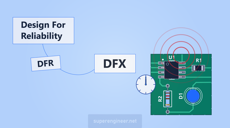
DFR (Design for Reliability) is a key aspect of reliability in electronics. It's worth getting to know this topic well, because DFR covers a number of really interesting subjects. In an electronics designer's day-to-day practice, the DFR approach means, among other things:
- Component derating (voltage, current, power, operating temperature range) with a margin appropriate for the mission profile.
- Selecting components for the environment, e.g., sulfur-resistant resistors where there is a high risk of silver sulfide formation, i.e., sulfur corrosion.
- Analyzing degradation mechanisms (solder joint cracking, CAF, electrochemical migration, corrosion, tin whiskers) instead of relying solely on theoretical assumptions and MTBF calculations.
- Validation through HALT and HASS testing.
- ESD and EOS protection at the schematic stage and later in the PCB layout.
- and much more.
IPC Standards
IPC (now the Global Electronics Association, see What is IPC?) has grouped its design standards into a few, let's say, "packages" such as: board design rules, DFM, materials and finishes, and advanced component packaging. It's a sensible split, because it matches the questions a designer asks: what kind of board am I building, can it be manufactured, what should it be made of, and what issues come with BGA, Flip-Chip, or BTC (QFN, LGA).
Product Class
When designing a product, you need to define its IPC product class (1, 2, or 3). This class later plays a key role in PCB fabrication (IPC-601x, IPC-A-600) and electronics assembly (J-STD-001 and IPC-A-610). See also IPC: Requirements flowdown and IPC: Order of precedence.
PCB Construction
The IPC-222x series of standards provides a range of recommendations related to the selection of materials, copper foil, panelization, electrical clearances, and component mounting requirements.
- IPC-2221 - generic requirements.
- IPC-2222 - rigid boards.
- IPC-2223 - flexible and rigid-flex boards.
- IPC-2226 - HDI boards
- IPC-2228 - RF/microwave boards.
More about IPC-222x in the article: IPC-222x - Basic Standards for Electronics Design.
DFM and DFA
Recommendations related to SMD footprints (land patterns), THT holes, and other guidance useful in PCB design come mainly from IPC-2231 (DFX guidelines), IPC-7351 (SMD land patterns), and IPC-7352 (land patterns for SMD and THT components).
Materials and Finishes
A series of standards related to PCB materials and finishes:
- IPC-4101 - specifications for base materials.
- IPC-4103 - high speed / high frequency laminates.
- IPC-4562 - copper foils.
- IPC-4552 - requirements for ENIG.
- IPC-4553 - requirements for immersion silver (ImAg).
- IPC-4554 - requirements for immersion tin (ImSn).
- IPC-4555 - requirements for OSP.
- IPC-4556 - requirements for ENEPIG.
Choosing the surface finish for PCB pads is not only a cost decision, but also a matter of quality and reliability. See Tin, HASL, ENIG, OSP and also: Moisture in PCBs.
Advanced Packaging
The IPC-709x series ties design to the assembly process for advanced (read: hard to assemble) packages: IPC-7091 (3D), IPC-7092 (embedded components), IPC-7093 (BTC: QFN, DFN, LGA), IPC-7094 (flip chip), and IPC-7095 (BGA).
An example of a BGA assembly problem is the Head in Pillow defect.
Tin Whiskers
High-reliability applications should account for the risk of a phenomenon called tin whiskers when using components with tin-plated leads (most parts) and when soldering with a lead-free alloy.
Ionic Cleanliness
Cleanliness of electronic assemblies is a very broad topic. It mainly concerns the concept of ionic cleanliness, which relates to the acceptable level of ionic contamination on the PCB surface that can lead to failure through a phenomenon known as electrochemical migration. The details are covered in the article: Cleanliness of PCB assemblies.
Conformal Coatings
Conformal coatings can extend the service life of electronic modules, but only if you make the right choice of conformal coating type and application method.
Summary
Electronics reliability is a very broad and complex topic. Standards and methods won't design a device for the engineer; they only help make decisions based on experience gathered across the industry, rather than on your own trial and error. D-FMEA shows where the risk is, and DFX and DFR methods suggest how to reduce it. IPC and IEC standards provide proven criteria and a common language between design and manufacturing.
As you can see, reliability has to be ensured at the product design stage. It's a unique combination of customer requirements, hands-on experience, D-FMEA, DFX (DFR) methods, and industry standards. Reliability in electronics is a very, very big and complex topic ;)
Footnotes
