

Introduction
In September 2020, a new version of the "H" IPC-A-610 standard was released. One of the significant changes is the removal of the Target condition. Why was the target condition removed from the IPC-A-610 standard, and what are the implications for the electronics industry? It is worth looking into.
IPC-A-610 target condition
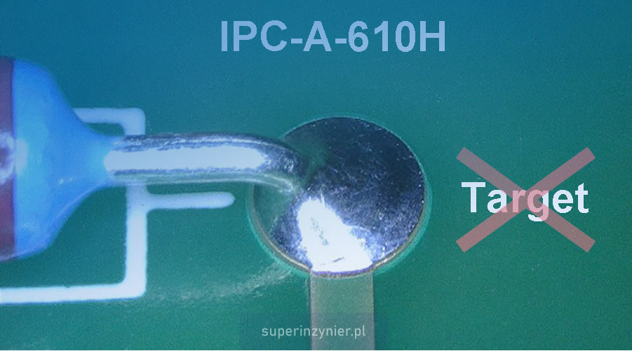
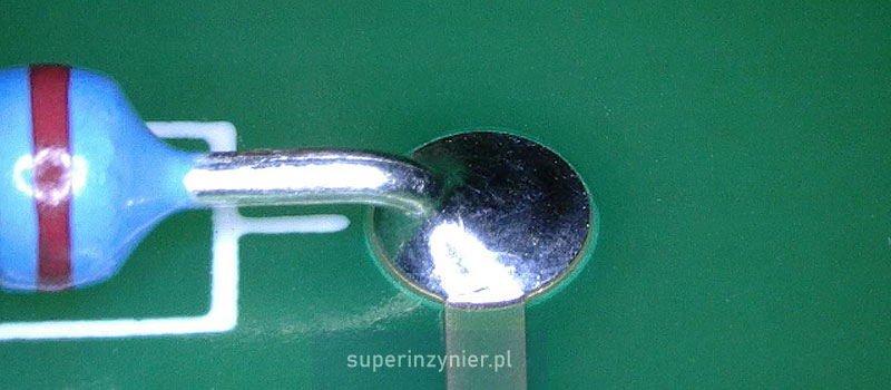
The target condition in the IPC-A-610 standard is an "ideal" situation, not always achievable. An example of such a condition is shown in the photo below, where we see a solder joint in that the solder covers 100% of the THT land on the PCB solder destination side, while there is a full circumferential wetting to the component lead and the THT land:
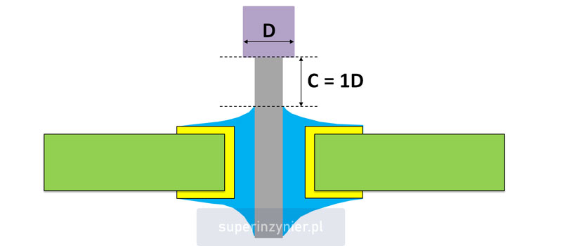
Another example of the target condition is when a wire is soldered to a circuit board, and the distance of the wire insulation from the solder (C) is exactly one wire diameter (D). The figure below shows this case:
IPC-A-610 revision H
The IPC organization removed the target condition from the IPC-A-610 standard in revision H (September 2020). It can also be said that the acceptable condition includes, among other requirements, the target condition requirements.
It is worth knowing that an acceptable condition is completely sufficient to ensure reliable operation of an electronic device. Such a condition can occur frequently and there is no reason to correct the assembled products.
I invite you to read the article IPC: Conditions explained, where various conditions are discussed with examples.
Why was the target condition removed?
The target condition has always seemed attractive in theory, but is often difficult to achieve in practice. Many times customers, users and stakeholders expect their products to look perfect, which often leads to unnecessary corrections of acceptable conditions.
Correcting acceptable conditions to meet target conditions is a bad practice. Here's why:
- Thermal shock for the components. Re-soldering component leads is another thermal shock to the structure of electronic components and the PCB itself. Any unnecessary stress contributes to reduced product reliability.
- Intermetallic growth. Re-melting of the solder joint leads to an increase in the thickness of the intermetallic layer, which reduces the mechanical strength of the solder joint and thus reduces its reliability.
- Flux contamination. Excess flux left on PCBs deteriorates ionic cleanliness and can be a source of electrochemical corrosion in the future.
- Increased cost. Correcting solder joints requires additional work, using additional materials and components. In some cases, attempts at unnecessary rework can cause such damage to the board that it becomes useless and must be scrapped. These are additional costs that can be avoided.
What is an intermetallic?
Intermetallic is an intermediate layer between the solder alloy and the base material of the component lead or PCB. This layer is formed as a result of the reaction between different solder materials and is essential for proper bonding during the soldering process.
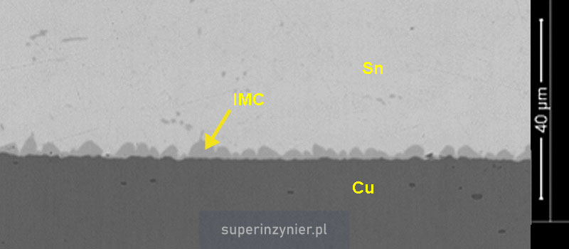
The electron microscope (SEM) image below shows a copper (Cu) and tin (Sn) solder joint with a clearly visible intermetallic layer (IMC):
Unfortunately, the intermetallic layer has a disadvantage - it is more brittle compared to the solder alloy or copper itself. The thicker the layer, the larger the area with "brittle" properties, which at the same time results in a decrease in the mechanical strength of the soldered joint.
During the soldering process it is important to get an intermetallic layer, and at the same time it is also important that this layer is not too thick. It is worth remembering that the intermetallic compound grows under the influence of heat, so repeated soldering leads to unnecessary growth of this layer.
Summary
The removal of the target condition from IPC-A-610 version H is intended to reduce instances of unnecessary correction of acceptable solder joints that may not look perfect, but still provide reliable performance.
Unnecessary correction of acceptable conditions leads to increased production costs and actually reduces the quality of products.
In conclusion, the removal of the target condition from version H of the IPC-A-610 standard is a step in the right direction. The question remains: how long will it take for operators, quality inspectors and, most importantly, customers to adjust to the fact that the acceptable condition is fully sufficient.
There is a proverb "Leave well enough alone" or "If it ain't broke, don't fix it", which fits perfectly with the topic of this article: it's worth remembering :)
