Introduction
Soldering is a fundamental process in electronics manufacturing, creating electrical and mechanical connections between components and PCB board. Traditionally, lead-based solders were very popular, but due to environmental and health concerns, lead-free solder alloys have become a new standard. Lead-free solder increases the magnitude of an effect called copper dissolution, which may become an issue for some specific applications.
This article explores the copper dissolution phenomenon, its implications in electronics soldering, and other areas where it may be relevant.
Copper dissolution mechanism
Copper dissolution refers to the phenomenon where copper from the substrate, typically a PCB solder land or copper-based component leads, dissolves into the molten solder during the soldering process.
Lead-free solder alloys, such as those containing tin (Sn), silver (Ag), tend to have higher melting points compared to traditional tin-lead (Sn-Pb) solders. The elevated temperatures accelerate the diffusion of copper atoms into the molten solder, leading to copper dissolution.
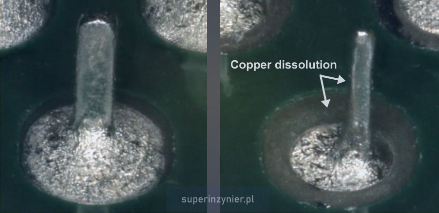
The photo shows two solder connections with different levels of copper dissolution. The solder joint on the right-hand side has a very severe copper dissolution effect. This specific example results from prolonged contact with the wave (molten solder) due to a soldering machine failure.

Factors affecting copper dissolution
Main factors are:
- Solder Composition. Lead-free solders, particularly those rich in tin, tend to dissolve copper more easily. Alloys such as SAC (Sn-Ag-Cu) are commonly used but are known for their aggressive interaction with copper.
- Temperature. Higher soldering temperatures increase the rate of copper dissolution[1]. Lead-free solders often require higher temperatures, worsening the effect
- Soldering Time. Prolonged exposure to molten solder increases copper dissolution. Reducing the time at liquidus temperature can mitigate this effect.
Solder joint reliability
Copper dissolution can compromise the overall reliability of solder joints. Brittle IMCs, weakened pads, and eroded leads collectively reduce the lifespan and durability of the soldered connections.
- PCB solder land integrity. Excessive copper dissolution can thin or completely remove copper pads on the PCB. It can compromise the solder joint's mechanical strength and lead to mechanical or thermal stress failures.
- Component lead erosion. Significant copper dissolution can erode the leads of components with copper leads, affecting the components' reliability and potentially leading to open electrical connections.
- Thicker intermetallic layer. The interaction between solder and copper forms intermetallic compounds (IMCs) at the interface. While a certain thickness of IMCs is desirable for a robust solder joint, excessive copper dissolution can lead to thick IMC layers, making the joint brittle and prone to failure.
Wave solder pot and copper dissolution
The wave soldering process uses a large pot containing molten solder. During soldering of wires, components, and PCBs, the copper surfaces come into contact with the molten solder, causing a small amount of copper to dissolve into the pot. In mass production, where many components and PCBs are soldered, the amount of copper having contact with the molten solder is substantial. The wave soldering process profile, primarily the solder pot temperature and the contact time, plays a role in limiting the effect.
As copper dissolves into the solder pot, the concentration of copper in the solder alloy increases over time. This incremental rise in copper content can alter the physical and chemical properties of the solder, impacting its wetting behavior, flow characteristics, and joint formation. An imbalanced copper concentration can lead to defects such as poor solderability, increased dross formation, and brittle solder joints, all of which degrade the quality and reliability of the final product.
Maintaining the copper concentration within a specified range is crucial to mitigating these issues. Follow industry standard IPC J-STD-001. It provides guidelines for soldering electronic assemblies, recommends regular monitoring and control of the contamination in the solder pot. In case of Pb-free alloys, the solder pot contamination limits (including Cu) shall be agreed between the manufacturer and the customer[2].
Example: For SAC305-type alloys, the manufacturers recommend[3] keeping the copper concentration below 1.0%. Exceeding the limit requires corrective actions, such as adding SAC300 solder bars (no Cu) to decrease copper concentration and restore optimal conditions.
Regular monitoring involves periodic sampling and analysis of the solder alloy to assess copper content. This proactive approach helps detect deviations from the recommended range early, allowing for timely corrective measures.
Rework and copper dissolution
Copper dissolution, particularly in the knee area of THT lands, can become a significant concern. This phenomenon becomes more noticeable when the rework time is very long or when multiple rework cycles are performed. It is just one of many reasons why it is crucial to properly train rework operators and provide adequate process controls for rework or repair, and modification of soldered connections.
Summary
In summary, managing copper dissolution in soldering is critical for maintaining the integrity and performance of solder joints. It is essential to understand the factors that influence copper dissolution and its effects on solder joint integrity. By optimizing soldering parameters and selecting appropriate solder alloys, the adverse effects of copper dissolution can be mitigated, leading to more robust and durable solder joints across various applications.
Regular monitoring and control of copper concentration, as per IPC-J-STD-001 guidelines, are essential for the wave soldering process to ensure high-quality, reliable electronic assemblies.
References
- S. Chada, R. Fournelle, W. Laub, and D. Shangguan, "Copper substrate dissolution in eutectic Sn-Ag solder and its effect on microstructure," Journal of Electronic Materials, vol. 29, pp. 1214-1221, 2000. Available: https://doi.org/10.1007/S11664-000-0015-6.
- IPC-J-STD-001, Rev.J, pt. 3.2.2
- MacDermid Alpha, "Alpha Vaculoy SAC300, 305, 350, 380, 387, 400, 405 Technical Bulletin," 06. Sept. 2023.


