 Polski
 English
Introduction
The soldering process requires meeting various requirements such as adequately heating components, cleaning the connection from metal oxides through flux, melting the solder alloy, and finally, cooling the solder joint.
Executing these conditions requires ensuring the appropriate temperature-time profile. Depending on the type of flux and solder alloy used in the selected solder paste, the profile requirements may vary slightly, but the fundamental principles remain the same. As known, lead-based alloys will have lower temperature and time values than most lead-free alloys.
Reflow soldering involves gradually heating the PCB, on which solder paste has been applied, and the components. In this process, the temperature is gradually raised to achieve reflow, and then it is cooled.
It is worth knowing that wave soldering is another process where the appropriate wave soldering profile is very important.
An incorrectly set soldering profile may lead in some cases to phenomena such as nonwetting or dewetting.
Types of profiles
The temperature-time profiles in reflow soldering process are divided into two types:
RSP
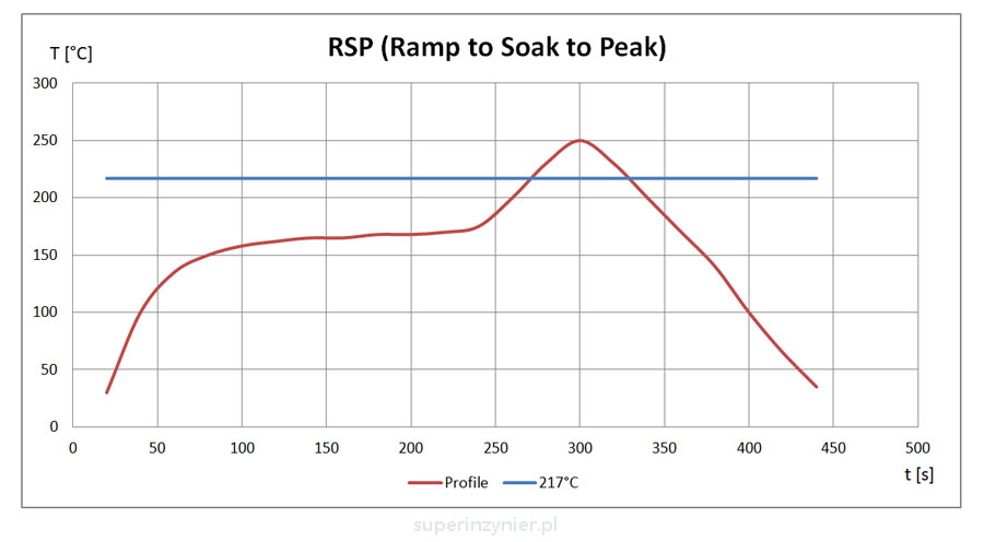
RSP (Ramp to Soak to Peak)[1]. This profile type is also known as RSS (Ramp Soak Spike). A characteristic feature is the visible soaking region, resembling a "saddle".
RP
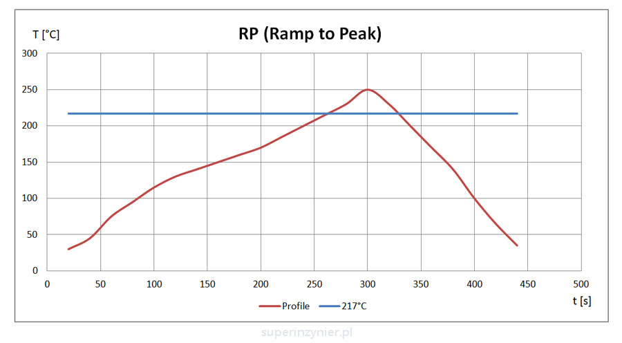
RP (Ramp to Peak)[1]. Also known as RTS (Ramp To Spike). The temperature rises almost linearly until it reaches the peak temperature. There is no visible soaking region.
Reflow soldering profile
The following description focuses on the RSP profile (with the "soak" region). We can distinguish the following stages of the reflow soldering process:
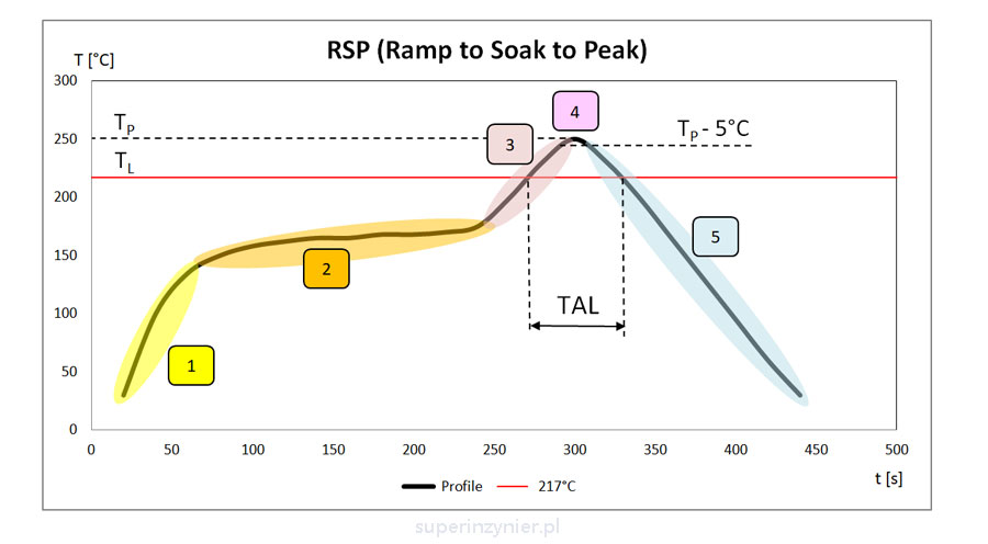
- Preheating [1] (Ramp up). The temperature gradient should not exceed 3°C/s[2], to avoid damaging sensitive electronic components[2] and enable the evaporation of the solvent from the flux. Typically, the heating gradient is 1-2°C/s.
- Soaking [2]. In this phase, the temperature rises much more slowly, allowing larger components to heat up and smaller elements not to be overheated. This evens out the temperature of the elements on the board. During this phase, the remaining volatile compounds evaporate, and the flux is activated. Cleaning of solder pads and component leads occurs. Depending on the type of flux in the paste, appropriate temperature and time ranges are established.
- Ramping to Peak [3]. After soaking, when the components are adequately heated, and the flux has performed its function, the temperature is raised until it reaches the peak value. Similar to the beginning of the profile, the temperature gradient should not exceed 3°C/s to avoid exposing sensitive components to potential damage.
- Reflow [4]. During the temperature rise "to the peak", solder melting occurs. The heat should be sufficient to ensure proper reflow and the creation of correct intermetallic phases. For lead-based alloys, the typical temperature range is 210-220°C, and for lead-free alloys, it is 230-245°C. In this phase, crucial parameters include:
- TAL (Time Above Liquidus). This is the time during which the solder alloy is in the liquid phase, above the melting temperature TL. The value of this time is in the range of 60-150s[2]. Paste manufacturers specify precise parameters depending on the alloy type and flux kind. Values like 30-90s, 45-60s, 60-90s, etc., can be encountered.
- Peak Temperature (TP). This is the maximum temperature that should not exceed the permissible range for components. The typical limit for components is 255-260°C. Always verify the maximum values specified by component manufacturers.
- Time within 5°C of the Actual Peak Temperature (TP-5°C). This time is related to the type of soldered components and their resistance to high temperatures. J-STD-020 standard defines this time within the range of 20-30s, with detailed guidelines provided by component manufacturers. This is associated with MSL qualification according to J-STD-020. The user must not exceed the given time, and the component manufacturer must ensure durability greater than the specified time.
- Cooling [5]. At this stage, the cooling gradient (Ramp down rate) should not exceed 6°C/s[2] (recommended 2-4°C/s), to avoid generating excessive stress for components. As before, always check the requirements of components and recommendations from the specific paste manufacturer.
Soldering profile monitoring
The profiling rules and methods of profiles monitoring are defined in IPC-7530 and IPC-7801.
Manufacturers of profilers offer software that supports semi-automatic profile optimization. Initially, it is necessary to download the profile from the actually soldered board, along with the air temperature readings. Then, precisely define the positions of individual oven zones, set temperatures and transport speed setting. Based on this data, the software will adjust optimal zone settings and transport speed for the specific product.
The latest versions of the software allow the analysis of multiple pre-developed profiles and the selection of a common oven setting for multiple product groups. This enables the optimization of product changeover times.
Summary
The reflow soldering profile should be selected based on the requirements defined by the solder paste manufacturer. Consideration should be given to the component distribution, differences in heating, and limitations associated with components (e.g., max temperature gradient, max peak temperature). The profile should be fine-tuned to minimize the voids and positioned as close as possible to the center of the process window.
If the product is intended to operate in very demanding conditions for many years, and soldered joints will be subjected to significant mechanical-thermal stresses, then it is important to use an appropriate oven. Reflow soldering profiles should be refined and regularly monitored in such cases.
References
- IPC-7530A
- IPC/JEDEC J-STD-020
